MPLS VPN Services
This article with aim to take a in depth look at MPLS and explain how your packets get from one side of the MPLS cloud to another. Hopefully this will give you some perspective that will prove useful in troubleshooting issues in your own MPLS implementations.
Most enterprise engineers MPLS experience goes something like this: The company needs to connect the office in Miami and the office in London with the corporate headquarters office in Chicago. The VPN design needs to be flexible, and most importantly the network connecting all 3 sites needs to be full mesh. By this I mean to say that any office should be able to talk to any other office using this MPLS VPN. At this point you contact your MPLS provider and ask them to provision 3 MPLS links, 1 for each of the above mentioned offices. The MPLS Sales team puts you in contact with their engineering department and they ask you a couple questions that they need answered in order to properly provision your lines. the number one question that they ask is “How do you want to send us routes?” �now depending on the size of your organization and the dynamic or static nature of your network you can opt for several options here are 3 of the most common.
-
Static Routes
-
BGP Peering
-
OSPF Peering
Now if your network is very small, say for instance you have 3 shoe stores that need to talk to the corporate office / warehouse, then you might opt for the static route option. If you are a large organization that is publicly traded and has a robust network and security policy in place you will most likely choose the second option as this gives you the most security and control over what routes enter and leave your network. �However the third option is also very popular, mainly because many organizations are already running OSPF, so this makes it that much easier to peer with the ISP. However using the same IGP to peer with your MPLS provider as you use to run your internal networks does leave you at risk. There are a host of vulnerabilities OSPF has that could be exploited even if you are using OSPF MD5 authentication such as LSA injection attacks. However the biggest reason not to do this is that if the ISP makes a mistake they could inadvertently dump hundred or thousands of routes into your routing table which could destabilize your entire network.
Now wouldn’t you know after all that negative talk about ospf peering. The example I am going to talk about below is exactly that OSPF peering.
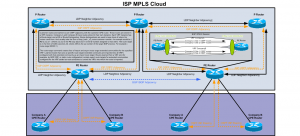
Please click on the above diagram for a larger view, you may want to download it as well and open it in a image view to zoom in on some of the smaller text and details.
In the example above you have 2 companies. To keep things simple we will call them Company A and Company B. Company A has 2 sites that need to communicate using MPLS, Company B also has 2 sites that need to communicate using MPLS. This ISP is lucky enough to get the business for both Company A and Company B. The ISP has a core network made up of an unspecified number of routers. In this example we will look at a small portion of the companies network. Our little piece of the network shows both customer sites connected to PE routers or (Provider edge) routers. These routers are responsible for providing access to the customers. The core of the network is made of P routers, or Provider routers. This provider has decided to convert their entire network to MPLS. This gives the ISP better performance by allowing the routers to utilize the ASICS built into the routers to switch the packets at incredible speeds. It also allows the ISP to offer many new services such as MPLS VPN’s as well as VPLS or (Virtual Private Lan Service.) In addition to these services the ISP can Use the tunneling aspect of MPLS to create Traffic engineering tunnels that will allow it to very precisely control which paths through the Provider network certain traffic takes. It also allows them to set very specific and granular QOS or COS policies for customers.
MPLS confuses many people because of its amorphous place in the OSI model. MPLs officially is a layer 2.5 protocol because Layer 3 protocols can be encapsulated in MPLS. MPLS stand for Multi Protocol Label Switching. MPLS can carry many different Layer 3 protocols inside it, just as ethernet a layer 2 protocol can carry TCP/IP inside its frames. However MPLS is more complicated than that. Many people can easily be confused because MPLs depends on the routing table in order to function, in this sense you could think of it like a layer 4 protocol. MPLS cannot function if the routing table is not working. MPLS depends on LDP or the Label Distribution Protocol to form adjacencies with neighbors and distribute its list of labels as well as receive labels from peers. LDP forms adjacencies at the layer 3 level and used the routing table to find peers. LDP is similar to OSPF in that is uses the highest Loopback address to identify itself. In our network Diagram each switch has a loopback address. All of the P routers including the PE routers are running OSPF. This OSPF instance is advertising the subnets owned by the ISP, many ISP’s use ISIS for this purpose, in fact many ISP’s use private addresses in their network especially if there network is a transit network. There are many situation in which you have public IP traffic traversing a private network connecting another public network. The 3 P routers and 2 PE routers need to know how to get to all of the non public IP addresses that the ISP is using to connect their network together. OSPF is used to synchronize these addresses as well as advertise each routers loopback address. Once all routers have formed neighbor relationships and all routes have been distributed through OSPF LDP is able to use the routing table to form adjacencies with other routers using their loopback addresses.
Once LDP has formed neighbor relationships with other routers using their loopback addresses it is able to start synchronizing the tag database. MPLS Assigns a tag or label to every route in the routing table. when a packet enters the MPLS PE routers interface, the router does a route lookup to determine the tag for the destination of the packet. Once this decision had been made, the router will push the tag on the packet and send it out the appropriate interface. The next router in line �has a simpler job. This router does not even have to look at the routing table, it can just look at its forwarding table and see what new tag should be assigned to the packet and send the packet on its way. the reason why this is so fast is because the MPLS tags were designed to look like layer 2 frames to the ASICS on the routers. This allows the programmers to leverage the same high speed chips used to route packets from one switch port to another based on mac addresses.
In MPLS the language is push and pop. to push a tag is to add a tag to a packet and to pop is to remove a tag from a packet.
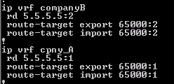
Once MPLS is working the ISP can begin to configure its client connections. To do this the ISP creates two VRF tables (Virtual Routing forwarding). The first VRF table we will call CompanyA and the second VRF table we will call CompanyB. It is important to add 2 things to each VRF table. The first thing is the route-target and the second is the route-discriminator. The route target is used by BGP as an extended community attribute. This lets BGP and other protocols determine what routes should be added to a VRF instance, and it also lets BGP know what routes are from a VRF instance.
This is important, because we need a way to get the routes from Company A site 1 into Company A site 2 router without mixing them up with routes from any other client. This is one of the key factors that lets two way route redistribution function correctly.
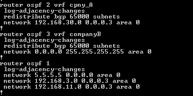
Once the VRF is created the next thing to do is go to the interface that connects the customer and add that interface to the Companies VRF. Once you do this the connected route for that interface should no longer show up on the main routing table. Once this step is complete it is time to configure a second instance of OSPF to communicate with the CPE equipment. this is done by specifying the VRF name when creating the new instance of OSPF.
Now that the OSPF adjacency is up with the customer you should be able to see a list of the routes under that VRF. The next step is to establish a BGP neighbor relationship with the other PE routers in the ISP or a Route Reflector depending on the size of the environment. Once the BGP relationship is established, the only thing you have to do is redistribute the OSPF routes into BGP and vice versa under the appropriate OSPF Instance.
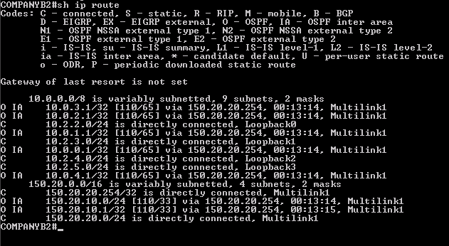
The end users should see the OSPF routes as simple IA routes. At the end of this post I will attach the full configs for all routers used incase you want to duplicate this in a lab or use GNS3 or Dynamips.
[caption id=“attachment_218” align=“alignleft” width=“631” caption=“Routes as seen by end USER or MPLS Subscriber”] [/caption]
Here are links to all the configs for all routers used in the lab –>Router Configs


